VCF 9.1 – HCX Configuration
In Part 1 we covered the deployment of HCX using the new VCF 9.1 Lifecycle process.
In this post I’ll demonstrate the configuration of HCX by linking Holodeck Site-A to Site-B and migrating a VM from one site to another.
First up, log into the site-a Holodeck HCX Manager at https://hcx-mgmt-01a.site-a.vcf.lab/
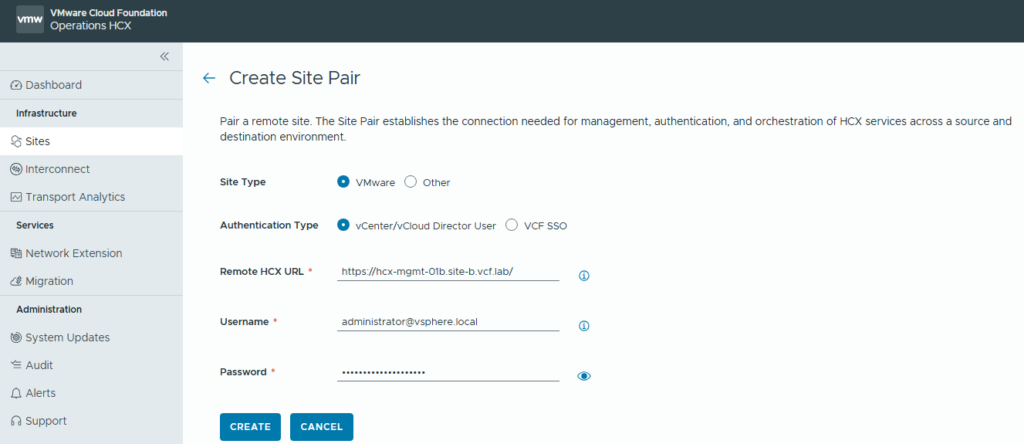
Browse to Sites and click on New Site Pair. Fill the Remote HCX URL with the site-b Holodeck HCX Manager URL.
When this process completes, we’ll see the site pairing listed.
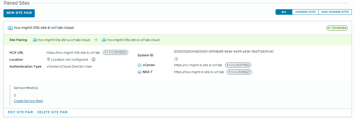
Note, the Site Pairing arrow only shows one direction from site-a to site-b, so this is a Uni-Directional site pairing. If we want to be able to migrate workloads back to site-a, we have to log into the site-b HCX Manager and create a pair back to site-a.
When we log into site-b, we will see the Uni-Directional pairing – arrow pointing in the other direction.

After we configure the reverse pairing:

Now we have the site pairing configured, we can start configuring the service mesh. The service mesh is the mapping of source & destination clusters, datastores and network uplinks for the HCX appliances.
For a simple demonstration I’ll be configuring 2 Network Profiles at each site (vMotion, and everything else), One compute profile at each site (source->target mappings).
Site-A Network Profiles:
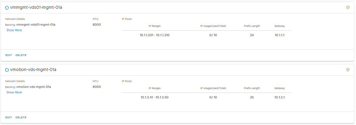
Site-B Network Profiles
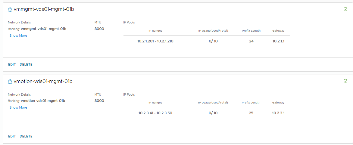
Note the enabled services in the vmmgmt profile:

The table below describes the Network Traffic types for HCX . You may want to assign different VLAN/Networks to different traffic types, for example – your network team may want Replication traffic to be routed over different network links to minimize contention with critical services, or you may want HCX Intersite Control to be on a secure internal link. You may also need to set a different MTU for different networks. I’m just going to run everything on the same network for simplicity.
The secure underlay setting will disable encryption – if you trust all the networks between the source and destination site, then you can enable secure underlay to reduce the performance impact of encryption.
| HCX Network Profile Types | Description |
|---|---|
| HCX Uplink | Used by Service Mesh components to reach their peer appliances. When destination HCX systems need to be reachable over the Internet, use the Uplink Network Profile to assign the Public IP addresses. Destination NAT configurations are not supported. The source HCX systems don’t need Public IP addresses and can be configured using traditional SNAT. |
| HCX Management | Used by Service Mesh components to connect to HCX Manager, vCenter Server, NTP, DNS. |
| HCX vMotion | Used by Service Mesh components to connect to the ESXi cluster for vMotion-based services. |
| HCX Replication | Used by Service Mesh components connect to the ESXi cluster for Replication-based services.This NP type is compatible with ESXi vSphere Replication VMkernel traffic but cannot be used for vSphere Replication NFC VMkernel traffic. |
| HCX Guest Network | In OSAM deployments, used by the Service Mesh Sentinel Gateway to connect to the Sentinel agents. |
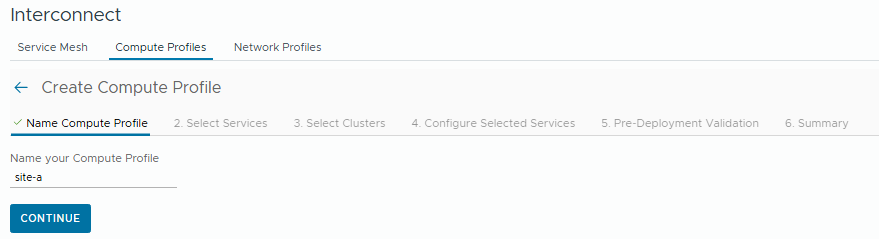
Now we’ll configure the compute profiles. Name the compute profile, then click continue.
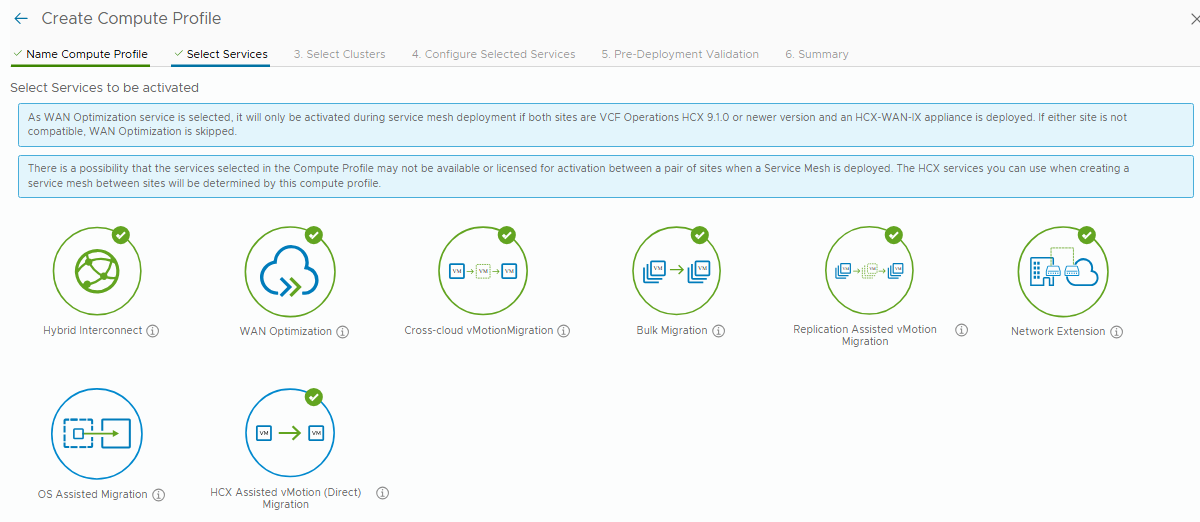
Select the services you want to enable in the compute mesh. Some services may be limited based on your license entitlement.
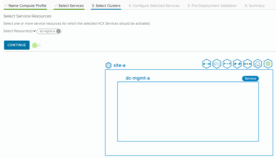
Next, select the clusters you want to make available for HCX Migration. I only have one in my lab – the mgmt domain.
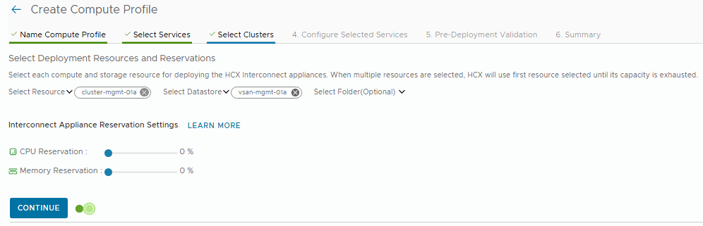
Next, we select the cluster/datastore where the HCX Interconnect appliances will be deployed. These appliances facilitate the HCX service functionality and link to paired appliances hosted at the remote/destination site.
Now we select the eligible network containers. I’m selecting the vds01 dvSwitch, and the MGMT Domain Overlay zone.
Note: a destination network when migrating a VM MUST be an NSX Overlay segment. It is not supported for the destination to be a dvPG or a VLAN Segment.
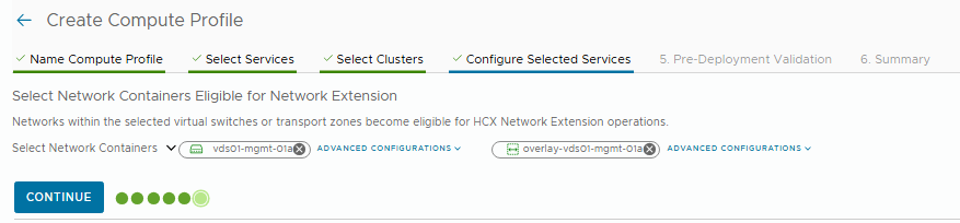
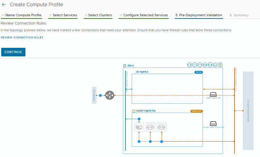
The final page of the wizard will perform a validation, and show a nice visualization of the interconnect appliances that will be deployed, and the corresponding network uplinks.
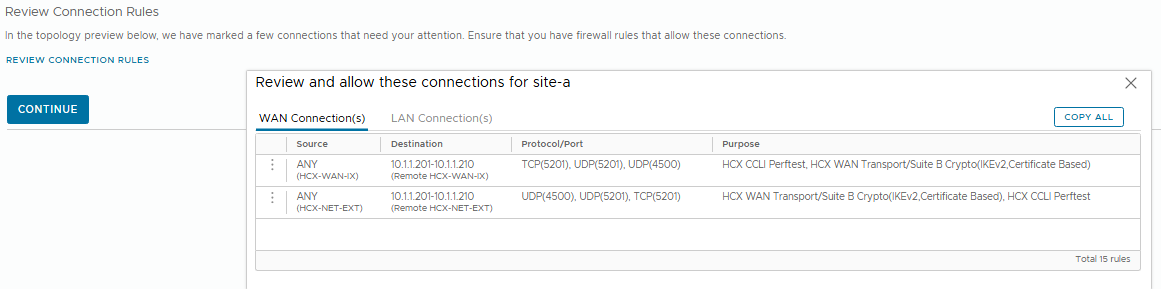
If you click “Review Connection Rules” this will show you a table of the required firewall rules to ensure connectivity.
Now I’ll repeat the same at site-b.
Now lastly we’ll configure the service mesh to activate the HCX services between site-a and site-b, which allows us to start migrations or create network extensions.
Browse to Service Mesh and click create.

Pick the source and destination compute profiles:
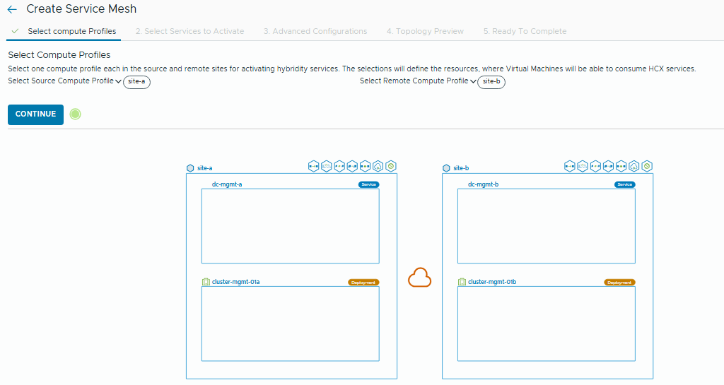
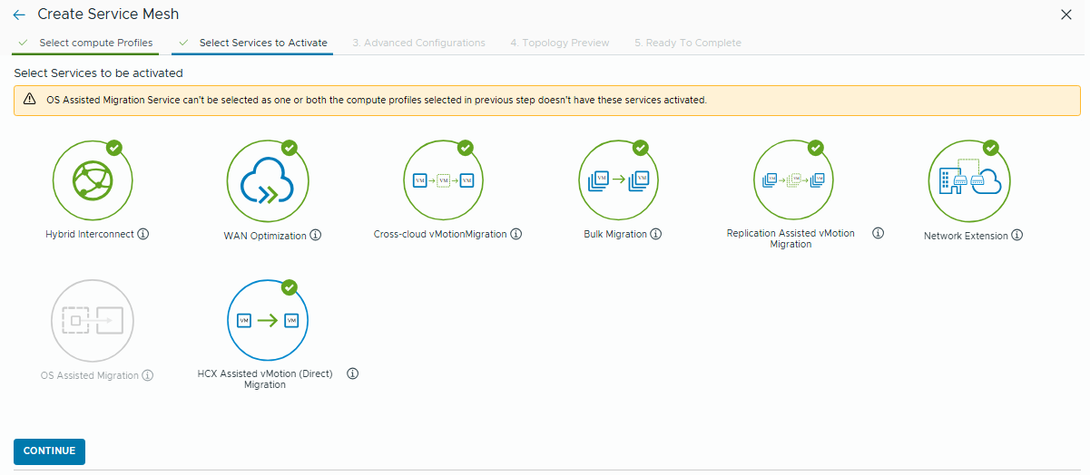
Select the services you want to enable. Only services that exist in the compute profiles of both sites will be shown.
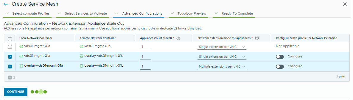
Next up, under advanced configuration you can override any of the network profiles specified in the compute profile.
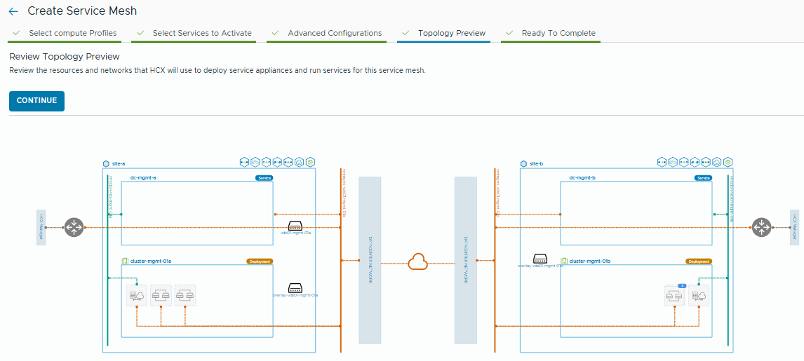
Topology preview will show a visual of the environments.
Lastly, name the service mesh and click “Create Service Mesh”
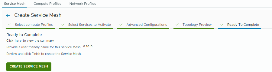
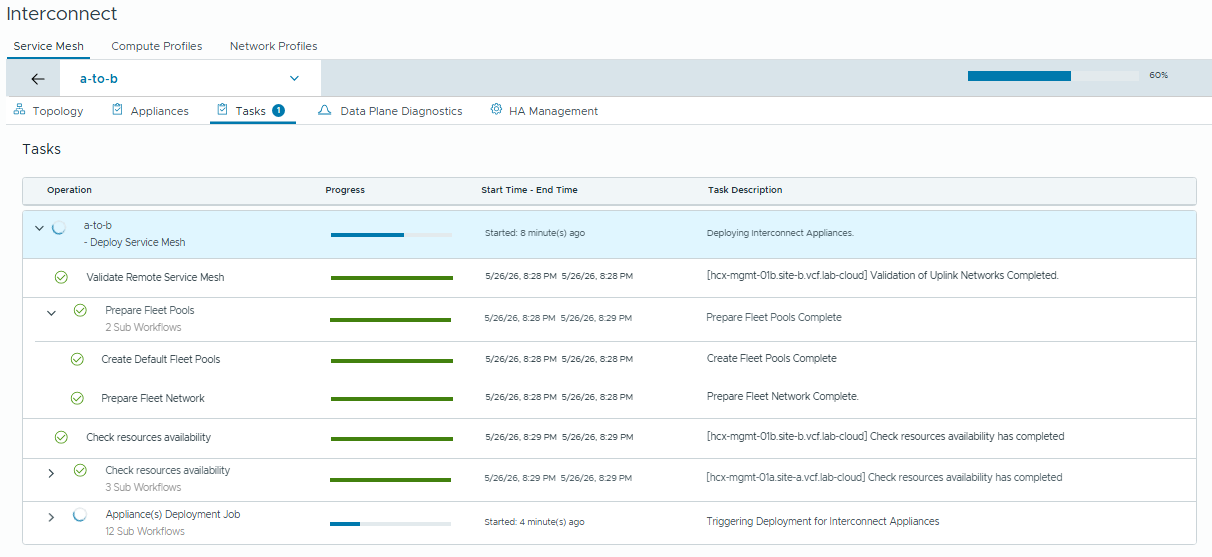
This will begin the interconnect appliance deployment. You can monitor the status from the “Tasks” tab.
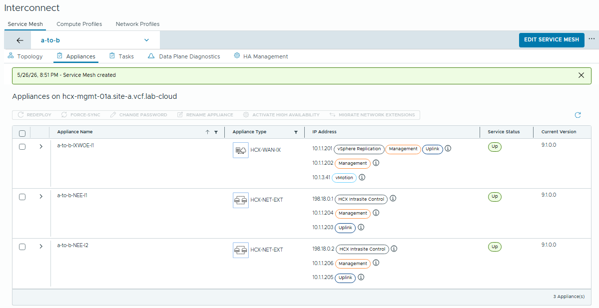
We can click on the Appliances tab to see which services are being provided by the deployed appliances:
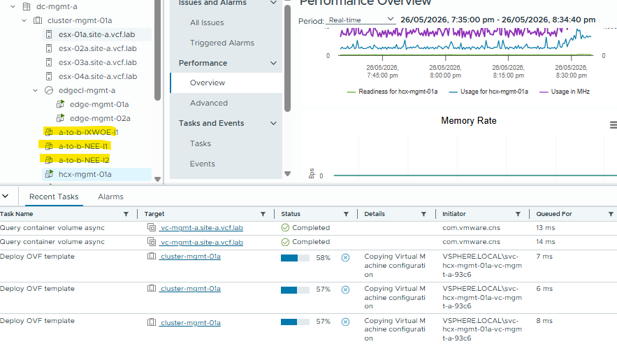
And we can see that these VMs have been deployed at both site-a and site-b in the respective vCenters:
That’s it, we should now be ready to migrate a workload from site-a to site-b (and back). In the next post I’ll demonstrate the workload migration.